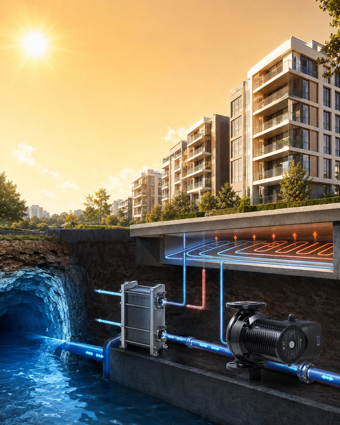
Mine-water cooling can turn abandoned mine water into a natural cooling source for buildings, but the cooling effect depends on more than water temperature. This article explains how heat exchangers, clean secondary loops, hydraulic design, dew-point control, and canned circulation pumps work together. Three AIKON CMS models are also presented as preliminary selection examples for similar clean-water circulation systems.
35°C Outside, 25°C Indoors Without Conventional Air Conditioning: The Circulation System Behind Mine-Water Cooling
Outdoor temperatures rise above 35°C, yet indoor temperatures remain at approximately 25°C without conventional residential air conditioning.
According to a public report, residents in Xuzhou, Jiangsu Province, are experiencing a different type of cooling system. Water in an abandoned mine remains at approximately 19°C and is being used as a natural cooling source. Through a heat-exchange station and radiant floor system, the cooling energy is delivered to residential buildings.
The underground low-temperature water is the most eye-catching part of the project.
However, from an HVAC engineering perspective, the more important question is:
How can cooling energy from underground water be delivered reliably to every building and every home?
The answer is not simply to pump mine water out of the ground.
Between the cooling source and the indoor terminal system, the cooling energy must pass through heat exchangers, secondary water circuits, circulation pumps, hydraulic balancing devices and radiant floor pipes.
The circulation pump plays a critical role in moving that cooling energy toward the building terminals.
Note: AIKON did not participate in the Xuzhou project discussed in this article. The public report is used only as a technical reference. The AIKON models listed below illustrate possible product ranges for similar clean-water secondary circulation systems and do not represent the actual equipment used in the project.
Why Can Mine Water Be Used for Building Cooling?
After a mine is closed, large amounts of water may remain underground.
Because the underground environment is less affected by seasonal outdoor temperature changes, this water may remain within a relatively stable temperature range.
In the publicly reported Xuzhou case, the mine water temperature was approximately 19°C. When outdoor temperatures exceed 35°C, the water can serve as a potentially useful natural cooling source.
However, mine water would not normally flow directly through the pipes beneath residential floors.
A more appropriate system design uses a heat exchanger to separate the mine-water circuit from the building-water circuit.
The mine water provides the cooling energy, while the building-side water transports that energy to the residential terminals.
How Does a Mine-Water Cooling System Work?
The system can be simplified into two hydraulically separated circulation loops.
Primary Side: Mine-Water Circulation
Mine water is transported to a heat-exchange station, where it releases cooling energy through a heat exchanger.
Because the primary circuit comes into direct contact with raw mine water, the pumps, pipes and other components must account for:
- sediment and suspended solids;
- dissolved minerals;
- corrosion and scaling risks;
- water pH;
- filtration and water-treatment methods;
- material compatibility.
For this reason, a pump for the mine-water side cannot be selected only by looking at flow and head.
Water-quality analysis, filtration requirements, pump materials and maintenance conditions must also be evaluated.
A standard HVAC circulation pump should not automatically be assumed suitable for untreated mine water.
Secondary Side: Clean Building-Water Circulation
Inside the heat exchanger, the mine water transfers cooling energy to a separate building-side water circuit.
The two liquids do not normally mix.
The secondary circuit generally carries treated water with characteristics close to clean water. The circulation pump moves this water through:
- the heat exchanger;
- supply and return mains;
- building pipework;
- control and balancing valves;
- distribution manifolds;
- radiant floor pipes;
- return-water circuits.
The simplified operating path is:
Low-temperature water in an abandoned mine
↓
Mine-water primary circuit
↓
Heat exchanger
↓
Clean building-side cooling water
↓
Building or zone circulation pump
↓
Radiant floor cooling pipes
↓
Return water to the heat exchanger
The position most strongly associated with AIKON CMS canned circulation pumps is the clean secondary-water circuit downstream of the heat exchanger.
Why Is a Circulation Pump Necessary When Low-Temperature Water Is Already Available?
A low-temperature water source only answers the question of where the cooling energy comes from.
Cooling energy cannot automatically pass through the heat exchanger or reach distant buildings and radiant floor circuits.
During circulation, the water must overcome resistance from:
- heat exchangers;
- pipe friction;
- elbows and fittings;
- filters;
- control valves;
- balancing valves;
- manifolds;
- radiant floor loops.
The circulation pump provides the differential pressure required to maintain the design flow.
When the flow is insufficient, a heat exchanger may have adequate cooling capacity while the building terminals still fail to receive enough cooling energy.
When the available pump head is too low, hydraulically unfavorable circuits, distant buildings or high-resistance zones may receive inadequate flow.
When the pump is oversized, the system may experience:
- excessive water velocity;
- pipe and valve noise;
- excessive differential pressure;
- difficult hydraulic balancing;
- unstable valve control;
- unnecessary circulation energy consumption.
Therefore:
Source-water temperature determines whether cooling energy is available. Circulation flow determines whether that energy can reach the terminals.
Is Building Height Equal to the Required Pump Head?
This is a common misunderstanding in circulation pump selection.
In a closed hydronic system filled with water, the static pressure created by water rising in the supply pipe is largely balanced by the water descending in the return pipe.
The circulation pump mainly overcomes friction and component pressure losses around the closed circuit. It does not continuously lift all the water to the top of the building.
For example, a 30-metre-tall building does not automatically require a circulation pump with 30 metres of head.
The correct method is to calculate the pressure loss of the hydraulically most unfavorable circuit, including:
- straight-pipe friction;
- elbows, tees and fittings;
- heat-exchanger pressure drop;
- filter pressure drop;
- control and balancing valves;
- radiant floor loops;
- other hydraulic components.
These pressure losses determine the required design head.
Why Are Canned Circulation Pumps Relevant to Building-Side Secondary Loops?
Pumps in residential cooling systems may be installed close to buildings, heat-exchange stations or indoor equipment rooms. They may also operate continuously throughout the cooling season.
These applications are concerned not only with flow and head, but also with operating noise, installation space, leakage risks and maintenance requirements.
Low-Noise Operation
Residential buildings, apartments, hotels and schools are sensitive to equipment noise.
A canned circulation pump uses a compact canned-motor structure and does not use the same exposed rotating-shaft arrangement found in many conventional pump designs. This makes it relevant to water circulation applications where low operating noise is important.
Actual system noise will still be affected by:
- whether the pump operates near an appropriate duty point;
- air trapped in the system;
- available inlet pressure;
- pipe support and vibration isolation;
- water velocity;
- excessive valve throttling;
- installation orientation.
A low-noise pump provides a suitable equipment foundation, but it cannot compensate for incorrect system installation or commissioning.
No Conventional Mechanical Shaft Seal
In a conventional centrifugal pump, the shaft generally passes from the motor into the pump chamber and therefore requires a shaft-sealing arrangement.
A canned circulation pump does not use the same exposed shaft and conventional mechanical seal structure, reducing one common potential leakage point.
However, flange connections, threaded joints, gaskets, pump bodies and pipework must still be installed and inspected correctly.
Compact Construction
Space is often limited in heat-exchange stations, packaged hydraulic modules and building equipment rooms.
Compact in-line circulation pumps are easier to integrate into heat-exchange units, heat-pump systems and prefabricated hydraulic assemblies.
Three-Speed Adjustment
Three-speed adjustment gives installers greater flexibility during commissioning.
The selected speed can be changed according to actual system flow, noise and terminal performance, allowing pump output to better match operating demand.
Three-speed adjustment is not equivalent to fully automatic variable-speed control, but it offers more flexibility than a fixed single-speed pump.
Suitable for Clean Hydronic Water
AIKON CMS pumps are designed for heating and air-conditioning circulation systems. The pumped liquid should be clean, free from solids and mineral oils, non-toxic, chemically neutral and close to the characteristics of water.
The general operating limits and product features listed in the AIKON CMS catalogue include:
- liquid temperature from +2°C to +110°C;
- maximum system pressure of 10 bar;
- IP44 protection;
- three-speed adjustment;
- low-noise operation;
- threaded and flanged models;
- optional pump-body materials;
- customized voltage and frequency options.
These characteristics create a strong application connection between the CMS range and clean secondary-water loops, building circulation circuits and zone circulation systems downstream of a heat exchanger.
Three AIKON CMS Model Examples
The following models illustrate preliminary performance ranges for secondary circulation circuits of different sizes.
The specifications above are taken from the AIKON CMS product catalogue.
CMS(L)25-8T1M-I: Small Zone Circulation
The CMS(L)25-8T1M-I uses a threaded connection, single-phase power supply and three-speed adjustment.
Its catalogue specifications include:
- maximum flow: 100 L/min, approximately 6 m³/h;
- maximum head: 8 m;
- maximum input power: 245 W;
- maximum system pressure: 10 bar;
- enclosure class: IP44.
It may enter preliminary screening for applications such as:
- small radiant floor cooling zones;
- single-floor or local circulation;
- compact heat-exchange modules;
- internal clean-water equipment circuits;
- distributed terminal hydraulic modules.
This model is more relevant to local circulation than to the centralized main circuit of a large residential development.
CMS(L)40-12F3M-II: Building or Heat-Exchanger Secondary Circulation
The CMS(L)40-12F3M-II uses a three-phase power supply, flanged connections and three-speed adjustment.
Its highest-speed catalogue specifications include:
- maximum flow: 304 L/min, approximately 18.2 m³/h;
- maximum head: 12.1 m;
- maximum input power: 760 W.
Compared with a small threaded pump, this model is closer to the preliminary performance range required for building-level circulation.
Potential applications include:
- small or medium residential building loops;
- secondary circulation between a heat exchanger and a building main;
- an independent building or cooling zone;
- circulation for a heat-pump or heat-exchange package;
- zoned hydronic circulation systems.
Final suitability must still be verified against the actual cooling load, water temperature difference, pipe resistance and standby-pump requirements.
CMS(L)50-16F3M-II: Larger Secondary Circulation Loops
The CMS(L)50-16F3M-II provides a larger flow and head range.
Its highest-speed catalogue specifications include:
- maximum flow: 485 L/min, approximately 29.1 m³/h;
- maximum head: 15.4 m;
- maximum input power: 1,400 W;
- three-phase 380 V power supply;
- flanged connection.
It may enter preliminary comparison for:
- larger residential building loops;
- combined circulation for several terminal zones;
- higher-resistance heat-exchanger circuits;
- commercial hydronic cooling systems;
- medium-sized energy or heat-exchange packages.
A large district energy station may still require pumps with greater capacity, multiple pumps in parallel or duty-and-standby configurations.
Maximum Flow and Maximum Head Do Not Occur at the Same Duty Point
The maximum flow and maximum head shown in a product catalogue are boundary values at different parts of the pump curve.
Maximum flow normally occurs in the lower-head region, while maximum head usually occurs near zero flow.
For example, when a project requires 18 m³/h at 11 m head, a model cannot be approved simply because:
- its maximum flow exceeds 18 m³/h; and
- its maximum head exceeds 11 m.
The correct selection method is:
Plot the required design flow and head as a duty point, then confirm that the point lies on the performance curve of the same speed setting and within a suitable continuous operating range
Why Does Radiant Floor Cooling Require Condensation Control?
Radiant floor cooling is not simply an underfloor heating system filled with cold water.
If the floor surface temperature falls below the indoor air dew point, moisture may condense on the floor or nearby pipe surfaces.
The system must therefore coordinate:
- supply-water temperature;
- return-water temperature;
- indoor temperature;
- indoor relative humidity;
- floor surface temperature;
- ventilation and dehumidification;
- dew-point sensors;
- pump and control-valve operation.
A lower supply-water temperature is not always better.
A more appropriate operating objective is:
Remove indoor heat through stable water circulation without allowing the floor surface to fall below the dew point.
The circulation pump transports the cooling water, but humidity and dew-point control must be handled by the complete building environmental control system.
Does a Natural Cooling Source Automatically Mean Low Energy Consumption?
A natural low-temperature water source can reduce the energy normally required to generate cooling through a refrigeration cycle.
However, the complete system still consumes electricity.
Electrical loads may include:
- mine-water extraction or primary-side circulation;
- building-side secondary circulation pumps;
- filtration and water-treatment systems;
- ventilation and dehumidification equipment;
- automatic control systems.
When a circulation pump is oversized, the system may still waste considerable energy even though the cooling source itself is natural.
When a pump is undersized, the terminal flow may be insufficient, preventing the system from making full use of the available natural cooling source.
Low-carbon cooling therefore requires not only a low-temperature energy source, but also correct hydraulic design and pump selection.
Conclusion
The mine-water cooling project in Xuzhou attracted attention because it transformed low-temperature water in an abandoned mine into a usable building cooling source.
However, the underground water alone is not what keeps the indoor environment comfortable.
A complete cooling process requires:
- mine water to provide the natural cooling energy;
- a heat exchanger to separate the primary and building circuits;
- circulation pumps to move clean secondary cooling water;
- pipe networks to distribute cooling energy to different buildings;
- radiant floor systems to absorb indoor heat;
- control systems to manage humidity, water temperature and condensation risks.
Mine water answers one question:
Where does the cooling energy come from?
The circulation pump answers another:
How can that cooling energy be delivered reliably to every terminal?
Natural cooling creates the potential for lower energy consumption. A reliable circulation system converts that potential into real indoor comfort.